Drone Kahlo

Implementation
.png)
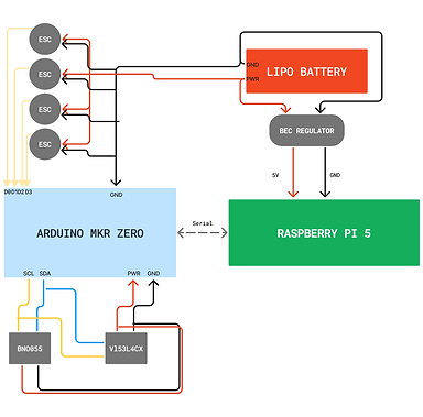
Hardware
We used and built quite a bit of hardware. Most importantly we made heavy modifications to a drone kit. This drone kit came with the drone chassis and ESC and motors already implemented, still we had our work cut out for us.
The relevant hardware is as listed:
-
Relevant Hardware:
Arduino Zero -
Versacopter Kit - Not Manufactured Anymore
-
LiPo Battery - 11.1V, 2.1A
-
RS2205 Motors * 4
Besides the COTS parts we integrated we designed several parts to allow all those parts to interact. These include:
-
Feet for the drone
-
Mounting plate for our compute and control
-
Protective cage to protect components and harnessing
-
Test jig for PID tuning and the mount constraining the drone
Software
We wrote all of our ROS2 packages from scratch.
ROS packages
pid_controller
The pid_controller package is responsible for controlling the drone's behavior to achieve stable flight and precise navigation by managing the inputs to its motors. It uses a Proportional-Integral-Derivative (PID) control system to adjust the drone's orientation and position based on sensor data and goal states.
Key Features:
-
State Management:
-
Tracks the drone's current state ([x, y, z, roll, pitch, yaw]).
-
Maintains error, integral, and derivative terms for PID calculations.
-
-
Sensor Integration:
-
Subscribes to:
-
/imu: Sensor data like roll, pitch, yaw.
-
/distance_sensors: Distance measurements from onboard sensors.
-
/path: Planned path or goal states from the planning node.
-
-
-
Control Outputs:
-
Publishes motor commands to /cmd using the MotorCommand message.
-
Computes motor inputs by translating PID control outputs into thrust, roll, pitch, and yaw adjustments using the drone’s mixer matrix.
-
-
Failsafe Mechanism:
-
Monitors critical thresholds (e.g., excessive tilt) and shuts down the drone if it drifts too far from equilibrium, ensuring safety.
-
-
Dynamic Parameter Selection:
-
After extensive debugging on Pitch PID tuning, we found out the constant jittering was due to the non-differentiable P and D functions across the state space, so we fit a sigmoid function to implement dynamic values when the drone is close to equilibrium.
-
-
Debugging Support:
-
Publishes debug information to /csv so that we can plot our gains against the drone behavior and understand how to tune the parameters
-
microcontroller
The microcontroller package acts as a bridge between the drone's onboard Arduino (or similar microcontroller) and the ROS 2 ecosystem. Its primary purpose is to handle low-level communication with the microcontroller, translating sensor readings and control commands into ROS messages and topics. This package facilitates real-time data exchange between the drone's hardware and other ROS nodes.
Key Features:
-
Command Handling:
-
Subscribes to the /cmd topic to receive motor control commands from the PID node.
-
Converts these commands into a format understood by the Arduino and transmits them over a serial connection.
-
-
Sensor Data Publishing:
-
Reads sensor data (e.g., IMU and distance sensors) from the Arduino via the serial interface.
-
Publishes this data to relevant ROS topics (/imu and /distance_sensors), making it accessible to other nodes.
-
-
Serial Communication:
-
Establishes a connection with the Arduino via a defined serial port (/dev/serial/...) at a baud rate of 115200.
-
Periodically polls the Arduino for new data using a timer, ensuring continuous updates.
-
-
Message Parsing:
-
Uses regular expressions to parse incoming serial data for:
-
IMU data (quaternions and gyroscope rates).
-
Distance sensor readings (e.g., depth).
-
-
Converts parsed data into appropriate ROS message formats.
-
-
Quaternion-to-Euler Conversion:
-
Converts quaternion IMU data into roll, pitch, and yaw angles for easier interpretation by higher-level control nodes.
-
planner
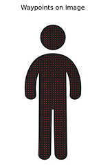
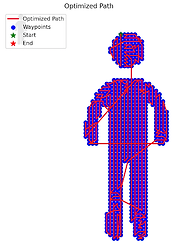
The path planning package is responsible for generating and publishing a path for the drone to follow based on a set of waypoints extracted from image data. It combines image processing, geometric computations, and ROS integration to create a navigable path for the drone.
Key Features:
-
Image Processing:
-
Extracts contours and waypoints from images using techniques such as Gaussian blurring, adaptive thresholding, and contour approximation. Fills it large spaces of areas that need to be painted by plotting waypoints in a grid pattern.
-
-
Waypoint Conversion:
-
Converts waypoints from pixel coordinates to real-world coordinates using a scale derived from the canvas dimensions and image resolution.
-
-
Path Planning:
-
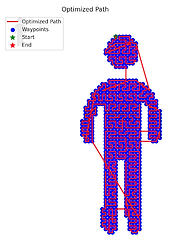
Implements a simple nearest-neighbor algorithm to construct a path that visits all waypoints efficiently.
-
Includes a straight line optimization that discourages turns along the drone’s flight path, yielding faster traversal.
-
-
Path Visualization:
-
Visualizes the computed path and waypoints using Matplotlib, aiding in debugging and development.
-
-
Path Publishing:
-
Publishes the generated path as a PoseArray message to the /path topic for use by other nodes (e.g., the PID controller).
-
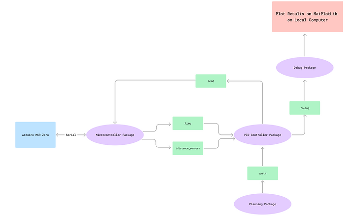
Overall Code Flow
One iteration of our entire pipeline would go as follows.
Note: Steps 1 and 2 only run once generally, but steps 3-7 loop over and over again
-
Planning Package
-
The planning package takes an image, and converts it into a series of waypoints. It then takes those waypoints and optimizes over the traveling salesman algorithm to plan a drone path from its current position to all relevant areas that need to be painted.
-
It then publishes this path to the relevant topic
-
-
ESC Initialization
-
The ESC’s run through a calibration sequence, which is the Arduino Setup Function.
-
-
Arduino Main Loop
-
Once the ESC’s initialize, the Arduino begins looping through the loop function, which simply prints the Sensor readings over Serial. It prints the distance sensor reading, and the IMU Quaternions, along with the Gyroscope data.
-
-
Microcontroller Package
-
The microcontroller package reads the Serial outputs, then sorts the values using Regex. It then publishes the sensor readings to the relevant topics
-
-
PID Package
-
The PID package subscribes to the path and sensor topics, and gets the current state of the drone, and attempts to drive it to the current point in the path.
-
Once it’s close enough to the point, it will switch to the next point in the path
-
In our implementation, the PID controller primarily attempts to drive the drone to equilibrium (roll = pitch = yaw = 0). The cartesian points are irrelevant to the equilibrium in this system, as it can be in equilibrium at any x,y,z.
-
The PID package then publishes the motor commands to the relevant topics
-
-
Microcontroller Package
-
The Microcontroller package subscribes to the motor command topic, and sends these values back to the Arduino
-
-
Arduino Main Loop
-
The Arduino Main Loop is constantly looking for values over serial to send to the motors
-
Relevant Launch Files and Commands:
ros2 run pid_controller control -> Runs the pid controller
ros2 run microcontroller arduino_node -> Starts serial connection and publishes sensor values
ros2 run debug ihatemyself -> subscribes to topics in pid controller to plot the drone attitude and pid values over time
.png)
.png)
.png)
.png)
Contours and
Edge Waypoints
Grid Waypoints
Nearest Neighbor
Optimized Path
Straight Line
Optimization
Full System Integration
.png)